WebGL Model-View-Projektion
Dieser Artikel untersucht, wie Sie Daten innerhalb eines WebGL-Projekts nehmen und sie in den richtigen Raum projizieren, um sie auf dem Bildschirm anzuzeigen. Er setzt Grundkenntnisse in der Matrizenmathematik unter Verwendung von Translations-, Skalierungs- und Rotationsmatrizen voraus. Der Artikel erklärt die drei Kernmatrizen, die typischerweise beim Zusammenstellen einer 3D-Szene verwendet werden: die Modell-, Ansichts- und Projektionsmatrix.
Die Modell-, Ansichts- und Projektionsmatrizen
Individuelle Transformationen von Punkten und Polygonen im Raum in WebGL werden von den grundlegenden Transformationsmatrizen wie Translation, Skalierung und Rotation gehandhabt. Diese Matrizen können zusammengefügt und in spezieller Weise gruppiert werden, damit sie für das Rendern komplizierter 3D-Szenen nützlich sind. Diese zusammengesetzten Matrizen bewegen letztlich die ursprünglichen Modelldaten in einen speziellen Koordinatenraum namens Clipspace. Dies ist ein 2 Einheiten breiter Würfel, zentriert bei (0,0,0), dessen Ecken von (-1,-1,-1) bis (1,1,1) reichen. Dieser Clipspace wird in einen 2D-Raum komprimiert und in ein Bild rasterisiert.
Die erste unten besprochene Matrix ist die Modellmatrix, die definiert, wie Sie Ihre ursprünglichen Modelldaten nehmen und im 3D-Weltraum verschieben. Die Projektionsmatrix wird verwendet, um Weltkoordinaten in Clipspace-Koordinaten umzuwandeln. Eine häufig verwendete Projektionsmatrix, die perspektivische Projektionsmatrix, wird verwendet, um die Effekte einer typischen Kamera nachzuahmen, die als Stellvertreter für den Betrachter in der 3D-virtuellen Welt dient. Die Ansichtsmatrix ist dafür verantwortlich, die Objekte in der Szene zu bewegen, um die Position der Kameraänderung zu simulieren und zu verändern, was der Betrachter derzeit sehen kann.
Die folgenden Abschnitte bieten einen detaillierten Einblick in die Ideen hinter und die Implementierung der Modell-, Ansichts- und Projektionsmatrizen. Diese Matrizen sind entscheidend für die Bewegung von Daten auf dem Bildschirm und sind Konzepte, die individuelle Frameworks und Engines überdauern.
Clipspace
In einem WebGL-Programm werden Daten typischerweise mit ihrem eigenen Koordinatensystem auf die GPU hochgeladen, und dann transformiert der Vertex-Shader diese Punkte in ein spezielles Koordinatensystem, das als Clipspace bekannt ist. Alle Daten, die über den Clipspace hinausgehen, werden abgeschnitten und nicht gerendert. Wenn jedoch ein Dreieck die Grenze dieses Raums überschreitet, wird es in neue Dreiecke aufgeteilt, und nur die Teile der neuen Dreiecke, die im Clipspace liegen, werden behalten.

Das obige Diagramm ist eine Visualisierung des Clipspace, in den alle Punkte passen müssen. Es ist ein Würfel mit zwei Einheiten auf jeder Seite, mit einer Ecke bei (-1,-1,-1) und der gegenüberliegenden Ecke bei (1,1,1). Der Mittelpunkt des Würfels ist der Punkt (0,0,0). Dieses 8 Kubikmeter große Koordinatensystem, das von Clipspace verwendet wird, ist als normalisierte Gerätekoordinaten (NDC) bekannt. Möglicherweise stoßen Sie bei der Recherche und Arbeit mit WebGL-Code gelegentlich auf diesen Begriff.
In diesem Abschnitt werden wir unsere Daten direkt in das Clipspace-Koordinatensystem einfügen. Normalerweise werden Modelldaten verwendet, die in einem beliebigen Koordinatensystem vorliegen, und dann werden sie durch Transformation mit einer Matrix umgewandelt, indem die Modellkoordinaten in das Clipspace-Koordinatensystem überführt werden. Für dieses Beispiel ist es am einfachsten zu veranschaulichen, wie Clipspace funktioniert, indem Modellkoordinatenwerte zwischen (-1,-1,-1) und (1,1,1) verwendet werden. Der untenstehende Code erstellt 2 Dreiecke, die ein Quadrat auf dem Bildschirm zeichnen. Die Z-Tiefe in den Quadraten bestimmt, was oben gezeichnet wird, wenn die Quadrate denselben Raum teilen. Kleinere Z-Werte werden über größeren Z-Werten gerendert.
WebGLBox-Beispiel
Dieses Beispiel erstellt ein benutzerdefiniertes WebGLBox-Objekt, das ein 2D-Rechteck auf dem Bildschirm zeichnet. Es wird als Klasse implementiert, die einen Konstruktor und eine draw()-Methode enthält, um ein Rechteck auf dem Bildschirm zu zeichnen:
class WebGLBox {
  canvas = document.getElementById("canvas");
  gl = this.canvas.getContext("webgl");
  webglProgram = createWebGLProgramFromIds(
    this.gl,
    "vertex-shader",
    "fragment-shader",
  );
  positionLocation;
  colorLocation;
  constructor() {
    const gl = this.gl;

    // Setup a WebGL program
    gl.useProgram(this.webglProgram);

    // Save the attribute and uniform locations
    this.positionLocation = gl.getAttribLocation(this.webglProgram, "position");
    this.colorLocation = gl.getUniformLocation(this.webglProgram, "vColor");

    // Tell WebGL to test the depth when drawing, so if a square is behind
    // another square it won't be drawn
    gl.enable(gl.DEPTH_TEST);
  }
  draw(settings) {
    // Create some attribute data; these are the triangles that will end being
    // drawn to the screen. There are two that form a square.

    // prettier-ignore
    const data = new Float32Array([
      // Triangle 1
      settings.left, settings.bottom, settings.depth,
      settings.right, settings.bottom, settings.depth,
      settings.left, settings.top, settings.depth,

      // Triangle 2
      settings.left, settings.top, settings.depth,
      settings.right, settings.bottom, settings.depth,
      settings.right, settings.top, settings.depth,
    ]);

    // Use WebGL to draw this onto the screen.

    // Performance Note: Creating a new array buffer for every draw call is slow.
    // This function is for illustration purposes only.

    const gl = this.gl;

    // Create a buffer and bind the data
    const buffer = gl.createBuffer();
    gl.bindBuffer(gl.ARRAY_BUFFER, buffer);
    gl.bufferData(gl.ARRAY_BUFFER, data, gl.STATIC_DRAW);

    // Setup the pointer to our attribute data (the triangles)
    gl.enableVertexAttribArray(this.positionLocation);
    gl.vertexAttribPointer(this.positionLocation, 3, gl.FLOAT, false, 0, 0);

    // Setup the color uniform that will be shared across all triangles
    gl.uniform4fv(this.colorLocation, settings.color);

    // Draw the triangles to the screen
    gl.drawArrays(gl.TRIANGLES, 0, 6);
  }
}
Die Shader sind die Stücke Code, die in GLSL geschrieben sind, die unsere Datenpunkte nehmen und letztlich auf dem Bildschirm rendern. Zur Bequemlichkeit sind diese Shader in einem <script>-Element gespeichert, das durch die benutzerdefinierte Funktion createWebGLProgramFromIds() in das Programm eingebracht wird. Diese Funktion übernimmt die grundlegenden Aufgaben, etwas GLSL-Quellcode zu nehmen und in ein WebGL-Programm zu kompilieren. Sie nimmt drei Parameter entgegen — den Kontext, in dem das Programm gerendert werden soll, die ID des <script>-Elements, das den Vertex-Shader enthält, und die ID des <script>-Elements, das den Fragment-Shader enthält. Diese Funktion wird hier nicht im Detail erklärt; wenn Sie ihre Implementierung sehen möchten, klicken Sie auf "Play" im Codeblock. Der Vertex-Shader positioniert die Eckpunkte, und der Fragment-Shader färbt jeden Pixel.
Werfen Sie zunächst einen Blick auf den Vertex-Shader, der die Eckpunkte auf dem Bildschirm bewegt:
// The individual position vertex
attribute vec3 position;

void main() {
  // the gl_Position is the final position in clip space after the vertex shader modifies it
  gl_Position = vec4(position, 1.0);
}
Um die Daten in Pixel zu rasterisieren, wertet der Fragment-Shader alles auf Pixelbasis aus und legt eine einzige Farbe fest. Die GPU ruft die Shader-Funktion für jeden Pixel auf, den sie rendern muss; die Aufgabe des Shaders ist es, die Farbe zurückzugeben, die für diesen Pixel verwendet werden soll.
precision mediump float;
uniform vec4 vColor;

void main() {
  gl_FragColor = vColor;
}
Mit diesen Einstellungen ist es an der Zeit, direkt mit Clipspace-Koordinaten auf dem Bildschirm zu zeichnen.
const box = new WebGLBox();
Zuerst zeichnen Sie eine rote Box in der Mitte.
box.draw({
  top: 0.5, // x
  bottom: -0.5, // x
  left: -0.5, // y
  right: 0.5, // y

  depth: 0, // z
  color: [1, 0.4, 0.4, 1], // red
});
Als nächstes zeichnen Sie eine grüne Box oben und hinter der roten Box.
box.draw({
  top: 0.9, // x
  bottom: 0, // x
  left: -0.9, // y
  right: 0.9, // y

  depth: 0.5, // z
  color: [0.4, 1, 0.4, 1], // green
});
Schließlich, um zu demonstrieren, dass das Abschneiden tatsächlich stattfindet, wird diese Box nicht gezeichnet, weil sie vollständig außerhalb des Clipspace liegt. Die Tiefe liegt außerhalb des Bereichs -1,0 bis 1,0.
box.draw({
  top: 1, // x
  bottom: -1, // x
  left: -1, // y
  right: 1, // y

  depth: -1.5, // z
  color: [0.4, 0.4, 1, 1], // blue
});
Die Ergebnisse
Übung
Eine hilfreiche Übung an dieser Stelle ist es, die Boxen im Clipspace herumzubewegen, indem Sie den Code variieren, um ein Gefühl dafür zu bekommen, wie Punkte im Clipspace abgeschnitten und bewegt werden. Versuchen Sie, ein Bild wie ein kastiges Smiley-Gesicht mit einem Hintergrund zu zeichnen.
Homogene Koordinaten
Die Hauptzeile des vorherigen Clipspace-Vertex-Shaders enthielt diesen Code:
gl_Position = vec4(position, 1.0);
Die position-Variable wurde in der draw()-Methode definiert und als Attribut an den Shader übergeben. Dies ist ein dreidimensionaler Punkt, aber die gl_Position-Variable, die schließlich durch die Pipeline weitergegeben wird, ist tatsächlich 4-dimensional — statt (x, y, z) ist es (x, y, z, w). Es gibt keinen Buchstaben nach z, daher wird diese vierte Dimension konventionell als w bezeichnet. Im obigen Beispiel wird die w-Koordinate auf 1,0 gesetzt.
Die offensichtliche Frage ist: "Warum die zusätzliche Dimension?" Es stellt sich heraus, dass diese Ergänzung viele schöne Techniken zur Manipulation von 3D-Daten ermöglicht. Diese hinzugefügte Dimension führt den Begriff der Perspektive in das Koordinatensystem ein; mit ihrer Hilfe können wir 3D-Koordinaten in den 2D-Raum abbilden – und so ermöglichen, dass zwei parallele Linien als sie in die Ferne verschwinden, sich schneiden. Der Wert von w wird als Divisor für die anderen Komponenten der Koordinate verwendet, sodass die tatsächlichen Werte von x, y und z als x/w, y/w und z/w berechnet werden (und w wird dann auch w/w, was 1 ergibt).
Ein dreidimensionaler Punkt wird in einem typischen kartesischen Koordinatensystem definiert. Die hinzugefügte vierte Dimension verwandelt diesen Punkt in eine homogene Koordinate. Sie stellt immer noch einen Punkt im 3D-Raum dar und es kann leicht demonstriert werden, wie man diesen Koordinatentyp durch ein Paar einfacher Funktionen konstruiert.
function cartesianToHomogeneous(point) {
  let x = point[0];
  let y = point[1];
  let z = point[2];

  return [x, y, z, 1];
}

function homogeneousToCartesian(point) {
  let x = point[0];
  let y = point[1];
  let z = point[2];
  let w = point[3];

  return [x / w, y / w, z / w];
}
Wie bereits erwähnt und in den oben genannten Funktionen gezeigt wird, teilt die w-Komponente die x, y und z-Komponenten. Wenn die w-Komponente eine nicht-null reelle Zahl ist, dann lässt sich die homogene Koordinate leicht wieder in einen normalen Punkt im kartesischen Raum umwandeln. Was passiert nun, wenn die w-Komponente null ist? In JavaScript würde der zurückgegebene Wert wie folgt lauten.
homogeneousToCartesian([10, 4, 5, 0]);
Dies ergibt: [Infinity, Infinity, Infinity].
Diese homogene Koordinate stellt einen Punkt im Unendlichen dar. Dies ist eine praktische Art und Weise, um einen Strahl zu repräsentieren, der aus dem Ursprung in eine bestimmte Richtung schießt. Neben einem Strahl könnte es auch als Repräsentation eines Richtungsvektors betrachtet werden. Wenn diese homogene Koordinate mit einer Matrix multipliziert wird, die eine Translation enthält, wird die Translation effektiv entfernt.
Wenn Zahlen auf Computern extrem groß (oder extrem klein) sind, beginnen sie ungenauer zu werden, da nur eine begrenzte Anzahl an Einsen und Nullen zur Darstellung verwendet wird. Je mehr Operationen an größeren Zahlen durchgeführt werden, desto mehr Fehler kumulieren sich im Ergebnis. Wenn man durch w teilt, kann dies die Genauigkeit sehr großer Zahlen effektiv erhöhen, indem auf zwei potenziell kleinere, weniger fehleranfällige Zahlen operiert wird.
Der endgültige Vorteil der Verwendung homogener Koordinaten ist, dass sie sehr gut zur Multiplikation mit 4x4 Matrizen passen. Ein Vertex muss mindestens eine der Dimensionen einer Matrix entsprechen, um mit ihr multipliziert werden zu können. Die 4x4 Matrix kann verwendet werden, um eine Vielzahl nützlicher Transformationen zu kodieren. Tatsächlich verwendet die typische perspektivische Projektionsmatrix die Division durch die w-Komponente, um ihre Transformation zu erreichen.
Das Abschneiden von Punkten und Polygonen aus dem Clipspace erfolgt, bevor die homogenen Koordinaten durch Division durch w in kartesische Koordinaten zurücktransformiert wurden. Dieser letzte Raum ist als normalisierte Gerätekoordinaten oder NDC bekannt.
Um mit dieser Idee zu beginnen, kann das vorherige Beispiel geändert werden, um die Verwendung der w-Komponente zu ermöglichen. Neben der Änderung von data sollten Sie auch daran denken, vertexAttribPointer() zu ändern, um 4 Komponenten zu verwenden (der zweite size Parameter) statt 3.
// Redefine the triangles to use the W component
// prettier-ignore
const data = new Float32Array([
  // Triangle 1
  settings.left, settings.bottom, settings.depth, settings.w,
  settings.right, settings.bottom, settings.depth, settings.w,
  settings.left, settings.top, settings.depth, settings.w,

  // Triangle 2
  settings.left, settings.top, settings.depth, settings.w,
  settings.right, settings.bottom, settings.depth, settings.w,
  settings.right, settings.top, settings.depth, settings.w,
]);
Dann verwendet der Vertex-Shader den 4-dimensionalen Punkt, der übergeben wird.
attribute vec4 position;

void main() {
  gl_Position = position;
}
Zuerst zeichnen wir ein rotes Rechteck in der Mitte, setzen aber w auf 0,7. Da die Koordinaten durch 0,7 geteilt werden, werden sie alle vergrößert.
box.draw({
  top: 0.5, // y
  bottom: -0.5, // y
  left: -0.5, // x
  right: 0.5, // x
  w: 0.7, // w - enlarge this box

  depth: 0, // z
  color: [1, 0.4, 0.4, 1], // red
});
Jetzt zeichnen wir ein grünes Rechteck oben, aber verkleinern es, indem die w-Komponente auf 1,1 gesetzt wird.
box.draw({
  top: 0.9, // y
  bottom: 0, // y
  left: -0.9, // x
  right: 0.9, // x
  w: 1.1, // w - shrink this box

  depth: 0.5, // z
  color: [0.4, 1, 0.4, 1], // green
});
Dieses letzte Rechteck wird nicht gezeichnet, weil es außerhalb des Clipspaces liegt. Die Tiefe ist außerhalb des Bereichs -1,0 bis 1,0.
box.draw({
  top: 1, // y
  bottom: -1, // y
  left: -1, // x
  right: 1, // x
  w: 1.5, // w - Bring this box into range

  depth: -1.5, // z
  color: [0.4, 0.4, 1, 1], // blue
});
Die Ergebnisse
Übungen
- Spielen Sie mit diesen Werten, um zu sehen, wie sie das auf dem Bildschirm gerenderte Bild beeinflussen. Beachten Sie, wie das zuvor abgeschnittene blaue Rechteck durch das Setzen seiner
w-Komponente wieder in den Bereich gebracht wird. - Versuchen Sie, ein neues Rechteck zu erstellen, das außerhalb des Clipspaces liegt, und bringen Sie es durch die Division durch
wwieder herein.
Modelltransformation
Punkte direkt in den Clipspace zu setzen hat nur begrenzten Nutzen. In realen Anwendungen haben Sie nicht alle Ihre Quellenkoordinaten bereits in Clipspace-Koordinaten. Meistens müssen Sie also die Modelldaten und andere Koordinaten in den Clipspace transformieren. Der bescheidene Würfel ist ein einfaches Beispiel dafür, wie man dies tun kann. Daten eines Würfels bestehen aus Eckpunktpositionen, den Farben der Würfelflächen und der Reihenfolge der Eckpunktpositionen, aus denen die einzelnen Polygone bestehen (in Gruppen von 3 Eckpunkten zur Konstruktion der Dreiecke, die die Flächen des Würfels bilden). Die Positionen und Farben werden in GL-Puffern gespeichert, als Attribute an den Shader gesendet und dann einzeln bearbeitet.
Schließlich wird eine einzelne Modellmatrix berechnet und gesetzt. Diese Matrix stellt die Transformationen dar, die auf jeden Punkt des Modells angewendet werden, um ihn in den richtigen Raum zu bewegen und alle anderen notwendigen Transformationen auf jeden Punkt im Modell durchzuführen. Dies gilt nicht nur für jeden Eckpunkt, sondern für jeden einzelnen Punkt auf jeder Oberfläche des Modells.
In diesem Fall bewegen eine Serie von Skalierungs-, Rotations- und Translationsmatrizen die Daten in jedem Frame der Animation in die gewünschte Position im Clipspace. Der Würfel hat die Größe des Clipspaces (-1,-1,-1) bis (1,1,1), daher muss er verkleinert werden, um nicht den gesamten Clipspace auszufüllen. Diese Matrix wird direkt an den Shader übergeben, nachdem sie zuvor in JavaScript multipliziert wurde.
Der folgende Codeausschnitt definiert eine Methode am CubeDemo-Objekt, die die Modellmatrix erstellt. Die neue Funktion sieht so aus (die Hilfsfunktionen werden im Kapitel Matrizenmathematik für das Web eingeführt):
function computeModelMatrix(now) {
  // Scale down by 20%
  const scaleMatrix = scale(0.2, 0.2, 0.2);
  // Rotate a slight tilt
  const rotateXMatrix = rotateX(now * 0.0003);
  // Rotate according to time
  const rotateYMatrix = rotateY(now * 0.0005);
  // Move slightly down
  const translateMatrix = translate(0, -0.1, 0);
  // Multiply together, make sure and read them in opposite order
  this.transforms.model = multiplyArrayOfMatrices([
    translateMatrix, // step 4
    rotateYMatrix, // step 3
    rotateXMatrix, // step 2
    scaleMatrix, // step 1
  ]);
}
Um dies im Shader nutzen zu können, muss sie an einer Uniform-Location gesetzt werden. Die Locations für die Uniforms werden im locations-Objekt unten gespeichert:
this.locations.model = gl.getUniformLocation(webglProgram, "model");
Und schließlich wird das Uniform an dieser Stelle gesetzt. Dies übergibt die Matrix an die GPU.
gl.uniformMatrix4fv(
  this.locations.model,
  false,
  new Float32Array(this.transforms.model),
);
Im Shader wird jeder Positionseckpunkt zuerst in eine homogene Koordinate (ein vec4-Objekt) transformiert und dann gegen die Modellmatrix multipliziert.
gl_Position = model * vec4(position, 1.0);
Hinweis:
In JavaScript erfordert die Matrizenmultiplikation eine benutzerdefinierte Funktion, während sie im Shader in die Sprache mit dem einfachen *-Operator eingebaut ist.
Der vollständige Orchestrierungscode ist verborgen. Wenn Sie interessiert sind, klicken Sie erneut auf "Play" in einem Codeblock in diesem Abschnitt, um ihn zu überprüfen.
Die Ergebnisse
Zu diesem Zeitpunkt beträgt der w-Wert des transformierten Punktes immer noch 1,0. Der Würfel hat noch keine Perspektive. Der nächste Abschnitt wird dieses Setup nehmen und die w-Werte ändern, um eine Perspektive zu bieten.
Übungen
- Verkleinern Sie die Box mit der Skalierungsmatrix und positionieren Sie sie an verschiedenen Orten innerhalb des Clipspaces.
- Versuchen Sie, sie außerhalb des Clipspaces zu bewegen.
- Ändern Sie die Fenstergröße und beobachten Sie, wie sich die Box verformt.
- Fügen Sie eine
rotateZ-Matrix hinzu.
Division durch W
Eine einfache Möglichkeit, etwas Perspektive auf unser Modell des Würfels zu bekommen, ist es, die Z-Koordinate zu nehmen und sie zu w zu kopieren. Normalerweise wird ein kartesischer Punkt zu homogenen Koordinaten umgewandelt, indem er zu (x,y,z,1) wird, aber wir werden ihn in etwas wie (x,y,z,z) ändern. Tatsächlich wollen wir sicherstellen, dass z größer als 0 ist für Punkte im Sichtfeld, daher werden wir es leicht ändern, indem wir den Wert zu ((1.0 + z) * scaleFactor) ändern. Dies wird einen Punkt, der normalerweise im Clipspace liegt (-1 bis 1), in einen Raum mehr wie (0 bis 1) verschieben, abhängig davon, auf welchen Wert der Skalierungsfaktor eingestellt ist. Der Skalierungsfaktor ändert den endgültigen w-Wert so, dass er entweder insgesamt höher oder niedriger ist.
Der Shader-Code sieht so aus.
// First transform the point
vec4 transformedPosition = model * vec4(position, 1.0);

// How much effect does the perspective have?
float scaleFactor = 0.5;

// Set w by taking the z value which is typically ranged -1 to 1, then scale
// it to be from 0 to some number, in this case 0-1.
float w = (1.0 + transformedPosition.z) * scaleFactor;

// Save the new gl_Position with the custom w component
gl_Position = vec4(transformedPosition.xyz, w);
Die Ergebnisse
Sehen Sie das kleine Dreieck an der Ecke in Richtung Kamera? Hier ist ein Screenshot von dem Moment, in dem es auftaucht:
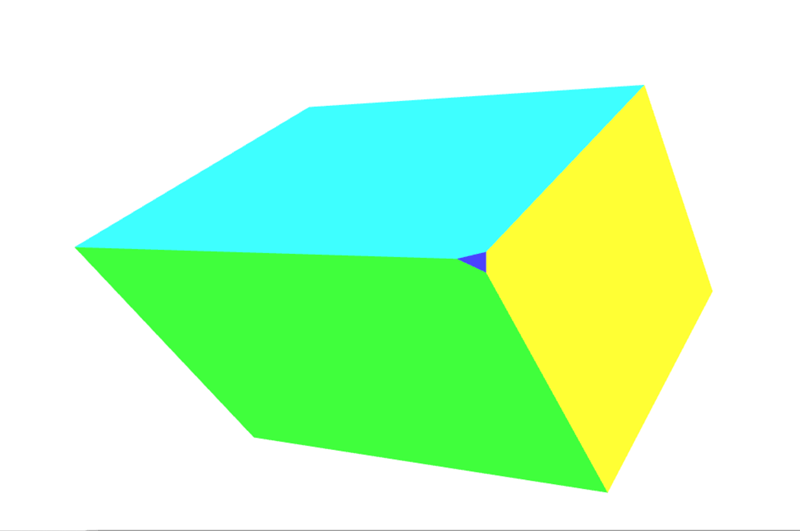
Das ist ein zusätzliches Gesicht, das unserem Objekt hinzugefügt wurde, weil die Rotation unserer Form dazu geführt hat, dass diese Ecke aus dem Clipspace herausragt, was zu dem Effekt führt, dass die Ecke abgeschnitten wird. Siehe Perspektivische Projektionsmatrix unten für eine Einführung, wie man komplexere Matrizen verwendet, um das Abschneiden zu kontrollieren und zu verhindern.
Übung
Wenn sich das ein wenig abstrakt anhört, öffnen Sie den Vertex-Shader und spielen Sie mit dem Skalierungsfaktor herum und beobachten Sie, wie er die Eckpunkte näher an die Oberfläche zieht. Völlig ändern Sie die w-Komponente-Werte für wirklich abgefahrene Raumdarstellungen.
Im nächsten Abschnitt werden wir diesen Schritt nehmen, bei dem Z in den w-Slot kopiert wird und es in eine Matrix verwandeln.
Einfache Projektion
Der letzte Schritt, das Auffüllen der w-Komponente, kann tatsächlich mit einer einfachen Matrix erreicht werden. Beginnen Sie mit der Einheitsmatrix:
// prettier-ignore
const identity = [
  1, 0, 0, 0,
  0, 1, 0, 0,
  0, 0, 1, 0,
  0, 0, 0, 1,
];

multiplyPoint(identity, [2, 3, 4, 1]);
// [2, 3, 4, 1]
Dann verschieben Sie die 1 in der letzten Spalte um einen Platz nach oben.
// prettier-ignore
const copyZ = [
  1, 0, 0, 0,
  0, 1, 0, 0,
  0, 0, 1, 1,
  0, 0, 0, 0,
];

multiplyPoint(copyZ, [2, 3, 4, 1]);
// [2, 3, 4, 4]
Es wurde jedoch im letzten Beispiel (z + 1) * scaleFactor durchgeführt:
const scaleFactor = 0.5;

// prettier-ignore
const simpleProjection = [
  1, 0, 0, 0,
  0, 1, 0, 0,
  0, 0, 1, scaleFactor,
  0, 0, 0, scaleFactor,
];

multiplyPoint(simpleProjection, [2, 3, 4, 1]);
// [2, 3, 4, 2.5]
Etwas weiter aufgeschlüsselt, können wir sehen, wie dies funktioniert:
const x = 2 * 1 + 3 * 0 + 4 * 0 + 1 * 0;
const y = 2 * 0 + 3 * 1 + 4 * 0 + 1 * 0;
const z = 2 * 0 + 3 * 0 + 4 * 1 + 1 * 0;
const w = 2 * 0 + 3 * 0 + 4 * scaleFactor + 1 * scaleFactor;
Die letzte Zeile könnte vereinfacht werden zu:
const w = 4 * scaleFactor + 1 * scaleFactor;
Dann faktorisieren wir den Skalierungsfaktor heraus, erhalten wir dies:
const w = (4 + 1) * scaleFactor;
Welche exakt dasselbe ist wie (z + 1) * scaleFactor, das wir im vorherigen Beispiel verwendet haben.
Im Box-Demo wird eine zusätzliche computeSimpleProjectionMatrix()-Methode hinzugefügt. Diese wird in der draw()-Methode aufgerufen und der Skalierungsfaktor wird an sie übergeben. Das Ergebnis sollte identisch mit dem letzten Beispiel sein:
function computeSimpleProjectionMatrix(scaleFactor) {
  // prettier-ignore
  this.transforms.projection = [
    1, 0, 0, 0,
    0, 1, 0, 0,
    0, 0, 1, scaleFactor,
    0, 0, 0, scaleFactor,
  ];
}
Obwohl das Ergebnis identisch ist, ist der wichtige Schritt hier im Vertex-Shader. Anstatt den Vertex direkt zu ändern, wird er mit einer zusätzlichen Projektionsmatrix multipliziert, die (wie der Name schon sagt) 3D-Punkte auf einer 2D-Zeichenfläche projiziert:
// Make sure to read the transformations in reverse order
gl_Position = projection * model * vec4(position, 1.0);
Die Ergebnisse
Der Betrachtungsfrustum
Bevor wir darauf eingehen, wie man eine perspektivische Projektionsmatrix berechnet, müssen wir das Konzept des Betrachtungsfrustums einführen (auch bekannt als Ansichtsfrustum). Dies ist der Bereich des Raums, dessen Inhalt für den Benutzer zum aktuellen Zeitpunkt sichtbar ist. Es ist der 3D-Raum, der durch das Blickfeld und die angegebenen Abstände als der nächste und entfernteste Inhalt definiert wird, der gerendert werden sollte.
Während des Renderings müssen wir bestimmen, welche Polygone gerendert werden müssen, um die Szene darzustellen. Genau das definiert das Betrachtungsfrustum. Doch was ist ein Frustum überhaupt?
Ein Frustum ist der 3D-Körper, der entsteht, wenn man einen beliebigen Körper nimmt und zwei Teile davon mit zwei parallelen Ebenen abschneidet. Betrachten Sie unsere Kamera, die einen Bereich betrachtet, der direkt vor ihrer Linse beginnt und sich in die Ferne erstreckt. Der sichtbare Bereich ist eine vierseitige Pyramide mit ihrem Gipfel an der Linse, ihren vier Seiten entsprechend den Grenzen ihres peripheren Sichtbereichs, und ihrer Basis an der entferntesten Entfernung, die sie sehen kann, wie hier:

Wenn wir dies verwenden würden, um die Polygone zu bestimmen, die in jedem Frame gerendert werden sollen, müsste unser Renderer jedes Polygon innerhalb dieser Pyramide rendern, den ganzen Weg bis ins Unendliche, einschließlich auch Polygone, die sehr nahe an der Linse sind — wahrscheinlich zu nah, um nützlich zu sein (und sicherlich einschließlich Dinge, die so nah sind, dass ein echter Mensch sie im selben Setting nicht fokussieren könnte).
Der erste Schritt, die Anzahl der Polygone zu reduzieren, die wir berechnen und rendern müssen, ist, diese Pyramide in das Betrachtungsfrustum zu verwandeln. Die zwei Ebenen, die wir verwenden, um Eckpunkte abzutrennen, um die Anzahl der Polygone zu reduzieren, sind die nahe Abschneidebene und die ferne Abschneidebene.
In WebGL werden die nahen und fernen Abschneidebenen definiert, indem der Abstand von der Linse zu dem nächsten Punkt auf einer Ebene angegeben wird, die senkrecht zur Betrachtungsrichtung steht. Alles, was näher an der Linse ist als die nahe Abschneidebene oder weiter von ihr entfernt als die ferne Abschneidebene, wird entfernt. Das ergibt das Betrachtungsfrustum, das so aussieht:

Der Satz der zu rendernden Objekte für jeden Frame wird im Wesentlichen erstellt, indem mit dem Satz aller Objekte in der Szene begonnen wird. Dann werden alle Objekte, die vollständig außerhalb des Betrachtungsfrustums liegen, aus dem Satz entfernt. Als nächstes werden Objekte, die teilweise aus dem Betrachtungsfrustum herausragen, abgeschnitten, indem alle Polygone entfernt werden, die vollständig außerhalb des Frustums liegen, und indem die Polygone, die außerhalb des Frustums hinausragen, so abgeschnitten werden, dass sie nicht mehr herausragen.
Sobald dies getan ist, haben wir die größte Menge an Polygonen, die vollständig innerhalb des Betrachtungsfrustums liegt. Diese Liste wird normalerweise weiter reduziert durch Verfahren wie Backface Culling (Entfernung von Polygonen, deren Rückseite zur Kamera zeigt) und Occlusion Culling unter Verwendung von Verdeckungsbestimmung (Entfernung von Polygonen, die nicht gesehen werden können, weil sie vollständig von Polygonen blockiert werden, die näher an der Linse sind).
Perspektivische Projektionsmatrix
Bis zu diesem Punkt haben wir unser eigenes 3D-Render-Setup Schritt für Schritt aufgebaut. Allerdings hat der aktuelle Code, wie wir ihn erstellt haben, einige Probleme. Zum einen wird er verzerrt, wann immer wir unser Fenster vergrößern oder verkleinern. Ein weiteres Problem ist, dass unsere einfache Projektion nicht mit einem breiten Wertbereich für die Szenendaten umgeht. Die meisten Szenen funktionieren nicht im Clipspace. Es wäre hilfreich, zu definieren, welche Distanz für die Szene relevant ist, um Präzisionsverluste beim Konvertieren der Zahlen zu vermeiden. Schließlich ist es sehr hilfreich, eine fein abgestimmte Kontrolle darüber zu haben, welche Punkte innerhalb und außerhalb des Clipspaces platziert werden. In den vorherigen Beispielen werden gelegentlich die Ecken des Würfels abgeschnitten.
Die perspektivische Projektionsmatrix ist eine Art Projektionsmatrix, die all diese Anforderungen erfüllt. Die Mathematik wird auch hier ein bisschen komplizierter und wird in diesen Beispielen nicht vollständig erklärt. Kurz gesagt, sie kombiniert die Division durch w (wie in den vorherigen Beispielen) mit einigen genialen Manipulationen basierend auf ähnlichen Dreiecken. Wenn Sie eine vollständige Erklärung der dahinterliegenden Mathematik lesen möchten, schauen Sie sich einige der folgenden Links an:
- OpenGL-Projektionsmatrix
- Perspektivische Projektion
- Versuch, die Mathematik hinter der perspektivischen Projektionsmatrix in WebGL zu verstehen
Ein wichtiger Punkt, den es zu beachten gilt, ist, dass die perspektivische Projektionsmatrix, die unten verwendet wird, die z-Achse umkehrt. Im Clipspace zeigt z+ vom Betrachter weg, während bei dieser Matrix z+ auf den Betrachter zukommt.
Der Grund, die z-Achse umzudrehen, ist, dass das Clipspace-Koordinatensystem ein linkshändiges Koordinatensystem ist (wobei die z-Achse vom Betrachter weg und in den Bildschirm zeigt), während die Konvention in Mathematik, Physik und 3D-Modellierung sowie für das Ansichts-/Augenkoordinatensystem in OpenGL darin besteht, ein rechtshändiges Koordinatensystem zu verwenden (z-Achse zeigt aus dem Bildschirm zum Betrachter). Mehr dazu finden Sie in den entsprechenden Wikipedia-Artikeln: Kartesisches Koordinatensystem, Rechte-Hand-Regel.
Werfen wir einen Blick auf eine perspective()-Funktion, die die perspektivische Projektionsmatrix berechnet.
function perspective(fieldOfViewInRadians, aspectRatio, near, far) {
  const f = 1.0 / Math.tan(fieldOfViewInRadians / 2);
  const rangeInv = 1 / (near - far);

  // prettier-ignore
  return [
    f / aspectRatio, 0, 0, 0,
    0, f, 0, 0,
    0, 0, (near + far) * rangeInv, -1,
    0, 0, near * far * rangeInv * 2, 0,
  ];
}
Die vier Parameter dieser Funktion sind:
fieldOfViewInRadians-
Ein Winkel, angegeben in Radianten, der angibt, wie viel von der Szene für den Betrachter gleichzeitig sichtbar ist. Je größer die Zahl, desto mehr ist sichtbar für die Kamera. Die Geometrie an den Rändern wird mehr und mehr verzerrt, äquivalent zu einem Weitwinkelobjektiv. Wenn das Sichtfeld größer ist, werden die Objekte typischerweise kleiner. Wenn das Sichtfeld kleiner ist, kann die Kamera immer weniger in der Szene sehen. Die Objekte werden viel weniger durch Perspektive verzerrt und erscheinen der Kamera näher.
aspectRatio-
Das Seitenverhältnis der Szene, das ihrem Breiten-zu-Höhen-Verhältnis entspricht. In diesen Beispielen ist das die Fensterbreite geteilt durch die Fensterhöhe. Die Einführung dieses Parameters löst endlich das Problem, bei dem das Modell verzerrt wird, wenn die Leinwand in der Größe verändert oder neu geformt wird.
nearClippingPlaneDistance-
Eine positive Zahl, die die Entfernung in den Bildschirm zu einer Ebene angibt, die senkrecht zum Boden steht, näher als die alles abgeschnitten wird. Dies wird im Clipspace auf -1 abgebildet und sollte nicht auf 0 gesetzt werden.
farClippingPlaneDistance-
Eine positive Zahl, die die Entfernung zu der Ebene angibt, über die Geometrie abgeschnitten wird. Dies wird im Clipspace auf 1 abgebildet. Dieser Wert sollte vernünftigerweise nahe an der Entfernung der Geometrie gehalten werden, um Präzisionsfehler beim Rendern zu vermeiden.
In der neuesten Version des Box-Demos wurde die Methode computeSimpleProjectionMatrix() durch die Methode computePerspectiveMatrix() ersetzt.
function computePerspectiveMatrix() {
  const fieldOfViewInRadians = Math.PI * 0.5;
  const aspectRatio = window.innerWidth / window.innerHeight;
  const nearClippingPlaneDistance = 1;
  const farClippingPlaneDistance = 50;

  this.transforms.projection = perspective(
    fieldOfViewInRadians,
    aspectRatio,
    nearClippingPlaneDistance,
    farClippingPlaneDistance,
  );
}
Der Shader-Code ist identisch mit dem vorherigen Beispiel:
gl_Position = projection * model * vec4(position, 1.0);
Zusätzlich (nicht gezeigt) wurden die Positions- und Skalierungsmatrizen des Modells geändert, um es aus dem Clipspace in das größere Koordinatensystem zu bringen.
Die Ergebnisse
Übungen
- Experimentieren Sie mit den Parametern der perspektivischen Projektionsmatrix und der Modellmatrix.
- Ersetzen Sie die perspektivische Projektionsmatrix, um Orthografische Projektion zu verwenden. Im MDN WebGL gemeinsamen Code finden Sie die Funktion
MDN.orthographicMatrix(). Diese kann die FunktionMDN.perspectiveMatrix()inCubeDemo.prototype.computePerspectiveMatrix()ersetzen.
Ansichts-Matrix
Während einige Grafikbibliotheken eine virtuelle Kamera haben, die positioniert und ausgerichtet werden kann, während eine Szene zusammengestellt wird, haben OpenGL (und in der Folge WebGL) dies nicht. Dies ist, wo die Ansichts-Matrix ins Spiel kommt. Ihre Aufgabe ist es, die Objekte in der Szene zu übersetzen, zu rotieren und zu skalieren, so dass sie relativ zum Betrachter in der richtigen Position sind, entsprechend der Position und Orientierung des Betrachters.
Eine Kamera simulieren
Dies nutzt eines der grundlegenden Gesichtspunkte von Einsteins spezieller Relativitätstheorie: das Prinzip der Bezugsrahmen und relativen Bewegung besagt, dass aus der Perspektive eines Betrachters es möglich ist, eine Veränderung der Position und Orientierung des Betrachters zu simulieren, indem die entgegengesetzte Änderung auf die Objekte in der Szene angewendet wird. In beiden Fällen erscheint das Ergebnis dem Betrachter identisch.
Betrachten Sie ein Rechteck, das auf einem Tisch steht, und eine Kamera, die einen Meter entfernt auf dem Tisch steht und auf das Rechteck gerichtet ist, dessen Vorderseite auf die Kamera zeigt. Betrachten Sie dann das Entfernen der Kamera vom Rechteck, bis sie zwei Meter entfernt ist (durch Hinzufügen eines Meters zur Z-Position der Kamera) und sie 10 Zentimeter nach links verschieben. Das Rechteck entfernt sich um diesen Betrag von der Kamera und rutscht leicht nach rechts, dadurch erscheint es kleiner für die Kamera und zeigt der Kamera eine kleine Menge seiner linken Seite.
Lassen Sie uns nun die Szene zurücksetzen, das Rechteck wieder in seine Anfangsposition bringen, mit der Kamera zwei Meter vom Rechteck entfernt, die direkt auf das Rechteck zeigt. Diesmal jedoch ist die Kamera auf dem Tisch fixiert und kann nicht bewegt oder gedreht werden. So ist es, in WebGL zu arbeiten. Wie simulieren wir also den Bewegung der Kamera im Raum?
Anstatt die Kamera rückwärts und nach links zu bewegen, wenden wir die inverse Transformation auf das Rechteck an: Wir bewegen das Rechteck einen Meter rückwärts und dann 10 Zentimeter nach Rechts. Das Ergebnis ist aus der Perspektive der beiden Objekte identisch.
Der letzte Schritt in all dem ist, die Ansichts-Matrix zu erstellen, die die Objekte in der Szene so transformiert, dass sie so positioniert sind, dass sie die aktuelle Kameraposition und -orientierung simulieren. Unser Code, wie er ist, kann den Würfel im Weltraum bewegen und alles perspektivisch projizieren, aber wir können immer noch die Kamera nicht bewegen.
Stellen Sie sich vor, Sie drehen einen Film mit einer physikalischen Kamera. Sie haben die Freiheit, die Kamera im Grunde beliebig zu platzieren und die Kamera in jede Richtung auszurichten, die Sie wünschen. Um dies in 3D-Grafiken zu simulieren, verwenden wir eine Ansichts-Matrix, um die Position und die Rotation dieser physikalischen Kamera zu simulieren.
Im Gegensatz zur Modellmatrix, die die Modellvertexe direkt transformiert, bewegt die Ansichts-Matrix eine abstrakte Kamera herum. In Wirklichkeit bewegt der Vertex-Shader immer noch nur die Modelle, während die "Kamera" in Position bleibt. Damit dies korrekt funktioniert, muss die inverse der Transformationsmatrix verwendet werden. Die inverse Matrix kehrt im Wesentlichen eine Transformation um, sodass wenn wir die Kameraansicht nach vorne verschieben, die inverse Matrix bewirkt, dass die Objekte in der Szene sich zurückbewegen.
Die folgende Methode computeViewMatrix() animiert die Ansichts-Matrix, indem sie sich vor- und zurückbewegt und nach links und rechts.
function computeViewMatrix(now) {
  const moveInAndOut = 20 * Math.sin(now * 0.002);
  const moveLeftAndRight = 15 * Math.sin(now * 0.0017);

  // Move the camera around
  const position = translate(moveLeftAndRight, 0, 50 + moveInAndOut);

  // Multiply together, make sure and read them in opposite order
  this.transforms.view = multiplyArrayOfMatrices([
    // Exercise: rotate the camera view
    position,
  ]);
}
Der Shader verwendet nun drei Matrizen.
gl_Position = projection * view * model * vec4(position, 1.0);
Nach diesem Schritt wird die GPU-Pipeline die außerhalb des Bereichs liegenden Eckpunkte abschneiden und das Modell zum Fragment-Shader zur Rasterisierung senden.
Die Ergebnisse
Beziehung zwischen den Koordinatensystemen
An diesem Punkt wäre es vorteilhaft, einen Schritt zurückzutreten, um die verschiedenen Koordinatensysteme, die wir verwenden, zu betrachten und zu kennzeichnen. Zuerst werden die Eckpunkte des Würfels in Modellraum definiert. Um das Modell in der Szene zu bewegen, müssen diese Eckpunkte in Weltraum umgewandelt werden, indem die Modellmatrix angewendet wird.
Modellraum → Modellmatrix → Weltraum
Die Kamera hat noch nichts getan, und die Punkte müssen erneut bewegt werden. Derzeit befinden sie sich im Weltraum, aber sie müssen in den Ansichtsraum verschoben werden (unter Verwendung der Ansichts-Matrix), um die Kameraplatzierung zu repräsentieren.
Weltraum → Ansichts-Matrix → Ansichtsraum
Schließlich muss ein Projektions (in unserem Fall die perspektivische Projektionsmatrix) hinzugefügt werden, um die Weltkoordinaten in Clipspace-Koordinaten zu überführen.
Ansichtsraum → Projektionsmatrix → Clipspace
Übung
- Bewegen Sie die Kamera innerhalb der Szene.
- Fügen Sie dem Ansichts-Matrix Rotationsmatrizen hinzu, um sich umzusehen.
- Schließlich verfolgen Sie die Position der Maus. Verwenden Sie 2 Rotationsmatrizen, um die Kamera nach oben und unten schauen zu lassen, basierend darauf, wo sich die Maus des Benutzers auf dem Bildschirm befindet.